This project involves DANGEROUSLY HIGH VOLTAGE at HIGH CURRENT!
This project requires the use of power tools.
Reflow temperatures are generally hotter than normal operation of the toaster
Soldering materials (of all types - this includes flux, solder - even lead free, PCB boards, etc) are TOXIC
In short:
Okay. So, I'm getting older. And so are my eyes. Not fun. And I don't have the world's best soldering station, either. In fact, what I have is a pencil iron, similar to what you might buy at Radio Shack (only better). Does not, have adjustable temperature control. Does not have replaceable tips. And I don't have $500 for a "good" station that will still get increasingly harder for me to use as my Mk I eyeballs deteriorate further.
It sure sucks getting old...
So, I want to be able to solder fine-pitch SMT parts. Not just SO-20's, but small 0402 resistors as well. Last time I tried soldering those was an experience, I'll tell you what. They were almost as likely to stick to my iron as they were to stick to the board, and burnt plenty of them in half. Yes, I'm solder trained, but I don't do those very often. And these days, they're getting harder to see.
What to do, what to do? Don't wanna give up the hobby... Hey, I know! Let's build a reflow oven!
So, here was the plan. Design a controller. Put it in a toaster oven. Voila! Reflow oven!
So, there I was, minding my own business, putting together a plan (Yikes! He's planning ahead! Look out!), and getting ready to build a new project that would be an enabler for future projects (all that new-fangled functionality seems to come in SMTs and BGAs, these days, dadgummit!).
So, I put together a couple of block diagrams, and started figuring out what I needed to do to make this thing work. Searched the internet to figure out what the reflow profiles look like, and found some other people who had done similar projects. This was comforting, it meant that the toaster oven would get warm enough to do the job.
Decided to use a PIC microcontroller (from Microchip) to do the control. Decided on a K type thermocouple as the temperature sensing device. Did some research on thermocouples. Turns out, that to do the job correctly, Id need an "ice reference" of some sort. Decided upon an Analog Devices AD595 to do the job. See the list of references at the bottom of this page - lots of interesting things about thermocouple use down there.
Figured out my user interface. This thing was gonna be fully buzzword 3.0 compliant, with three preset curves (Pb/Sn, ROHS, and one manual-entry control curve), an LCD on the front, and RS232 communication, so I could monitor temperature profile via PC.
put together some block diagrams to represent how the software would work.
Even got so far as selecting 90% of my parts. Total cost (with >90% certainty) would be about $400 (this includes the fact that I had many of the parts "on the shelf" already).
Was just starting to put together schematics, when a friend at work pointed this company that sells PID Ramp/Soak controllers for ~$75. These kinds of controllers normally go for no less than about $500US, so this was quite a surprise.
Dammit, Ryan, I think you just screwed up a perfectly good project. Unfortunately, the documentation for that project left something to be desired - it was Chinese translated to English, so pretty hard to follow. Also, the product I really wanted (to fit inside the oven housing), the JLD633 was out of stock. Looked around some more, and found another company that sold a similar product (American made... Or at least the documentation is...) for the same price... And this unit would fit in the oven chassis. And they also sold the thermocouples (cheaper than I could find anywhere else), SSRs, and SSR heat sinks. Wow. Total cost (including a spare thermocouple and the toaster oven) would be right about $200US.
Well, then... This required some thought. Do I go ahead with tthe original plan, build everything myself, and learn to control the LCD, and do floating point math on the PIC, or do I integrate the components from Auber Instruments, and save the $200 for some other project?
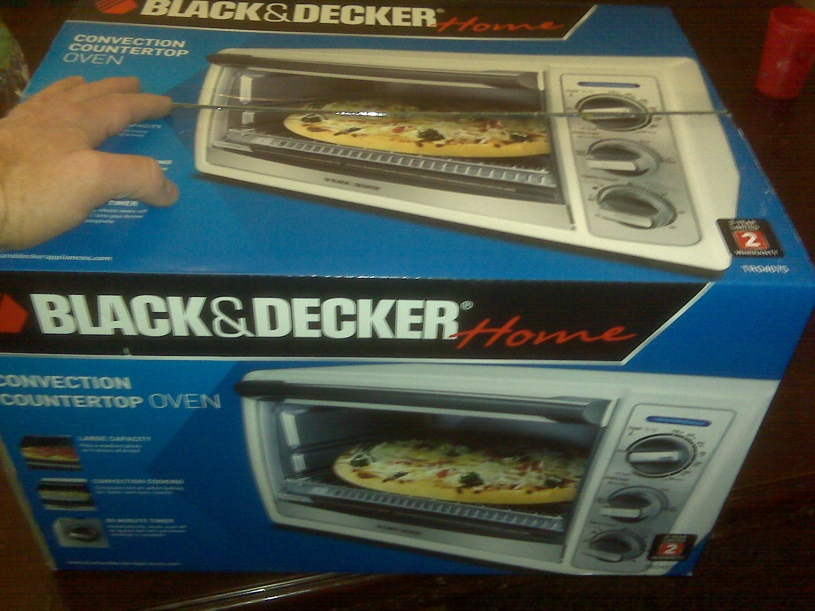
Well, it was the latter. Spent $153.85US (including shipping) with Auber, and had the stuff at my door in about three days. Went to Wal*Mart and bought a Black & Decker toaster oven (with internal fan to minimize hot spots), and integrated the system. It took me less than a day to put it all together. Took me part of another day to get a reasonable control profile (PbSn) out of it.
So, here you go - here's how I put it together, in pictures.
Opening the box:
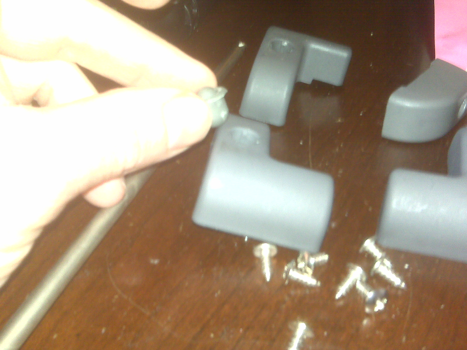
Removing the screws is interesting. First off, notice the bottom-most screw on the back is not a phillips, but a "star." I think they did this to keep morons like me from craking the case open.
The next trick is the LRF (Little Rubber Feet) option that's installed on this toaster. These little plugs pull out to access the screws underneath.
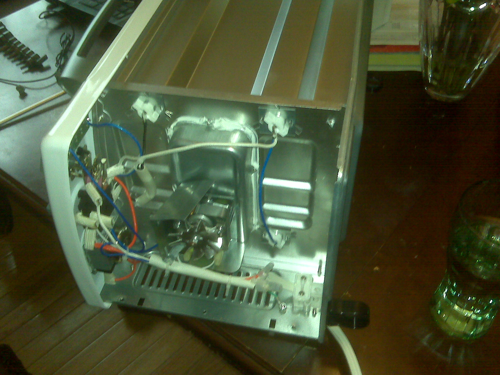
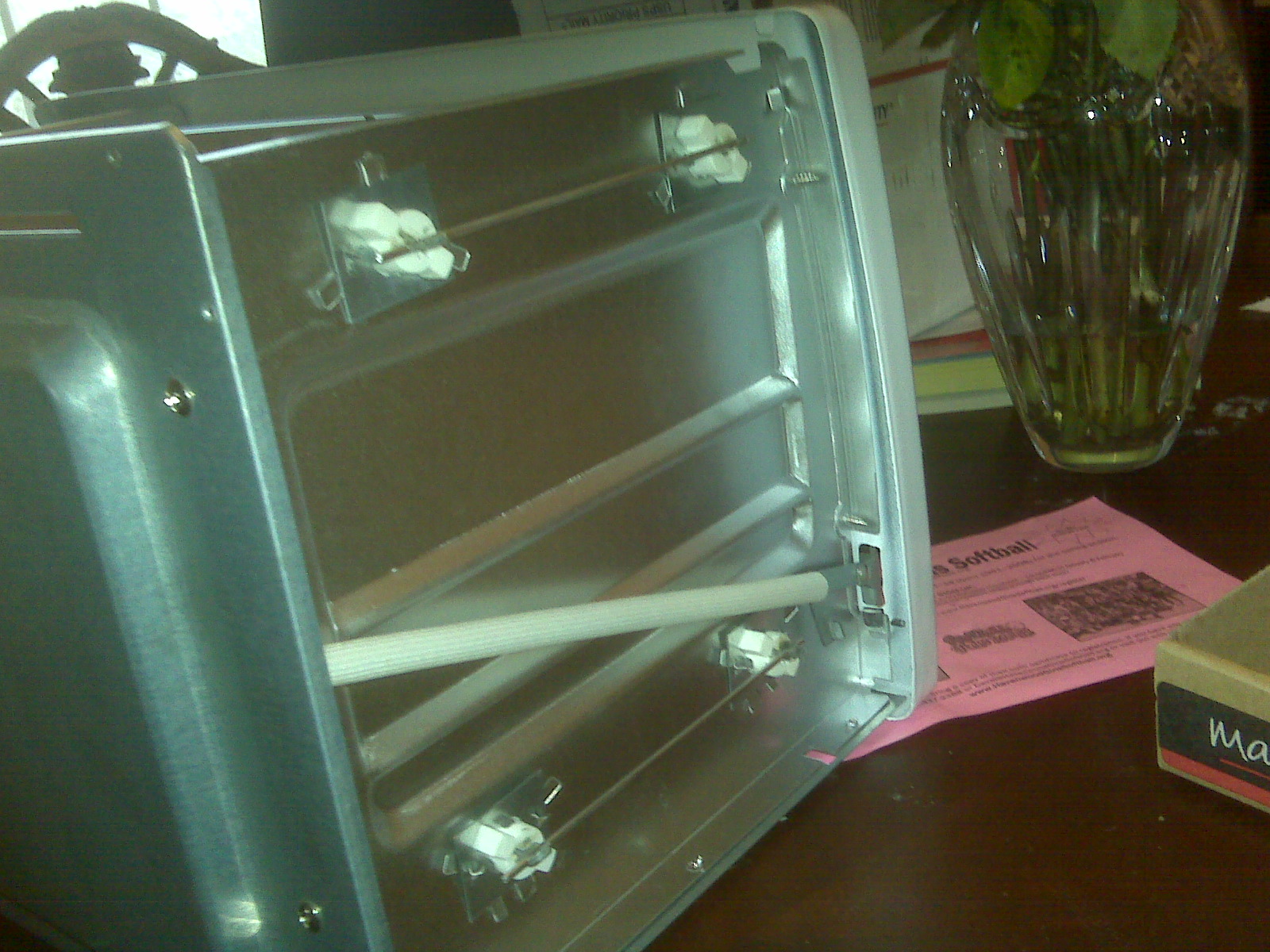
Once the cover is removed, you can see the innards. There ain't much in there. The little fan is to keep the motor cool. The inside of the controller cavity will get warm. I dunno if the controller has an ice point reference in it or not, so to be sure things stay stable, you should probably allow a full cool-down between reflows. To the far left, you can see the backs of the controls. See the thermal shield around the black wire? That's a fusible link in there. I took it out.
The far side of the oven - You can see the metal bars soldered to connect the heater elements in pairs (top and bottom). The long white thing is the hinge mechanism - it's attached to a spring in the back.
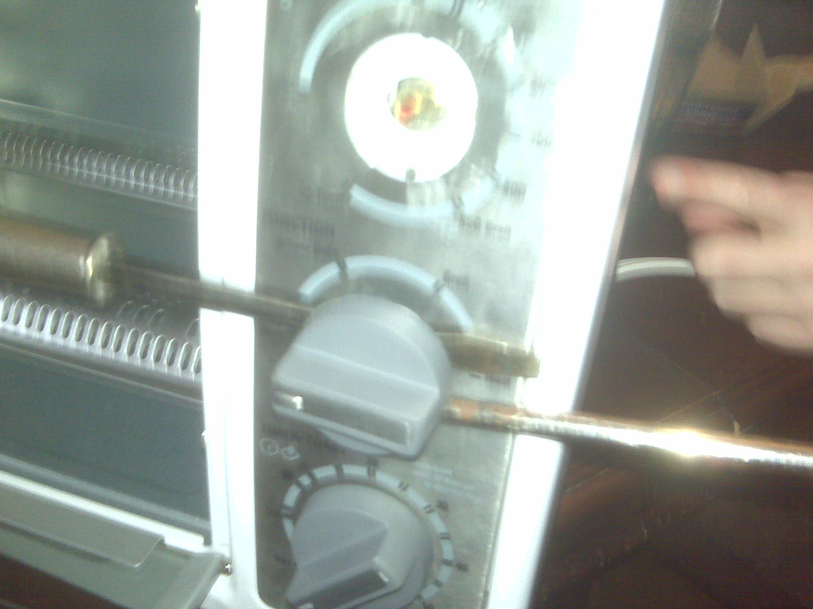
Now that the cover is off, it's time to pull off the knobs. This is easily done by inserting two standard screwdrivers and prying up opposite each other.
Once the knobs are off, look inside. See those metal tabs? Straighten them out as best you can, and the metal cover will pop right off the front.
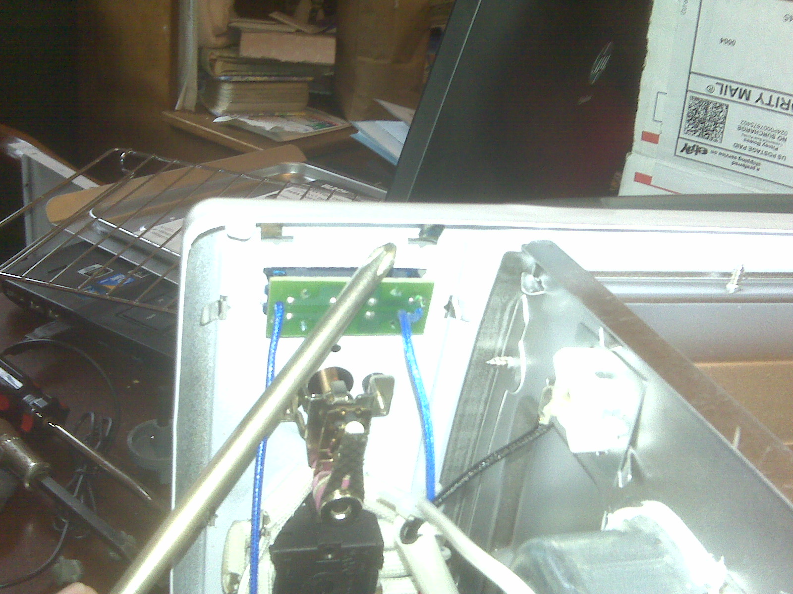
Now that the control cover is off, it's time to take out the controls. They are held on by these #2 Phillips screws.
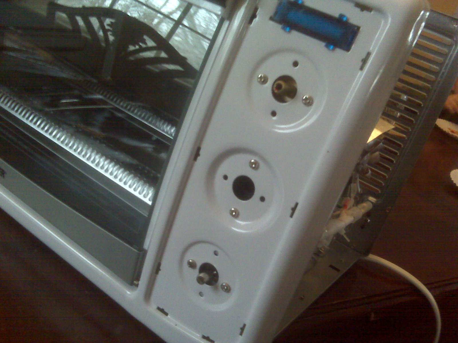
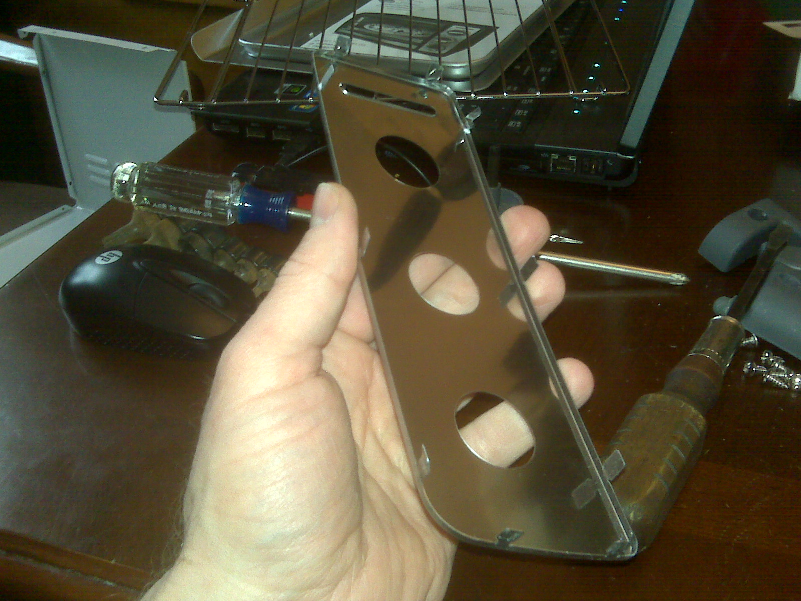
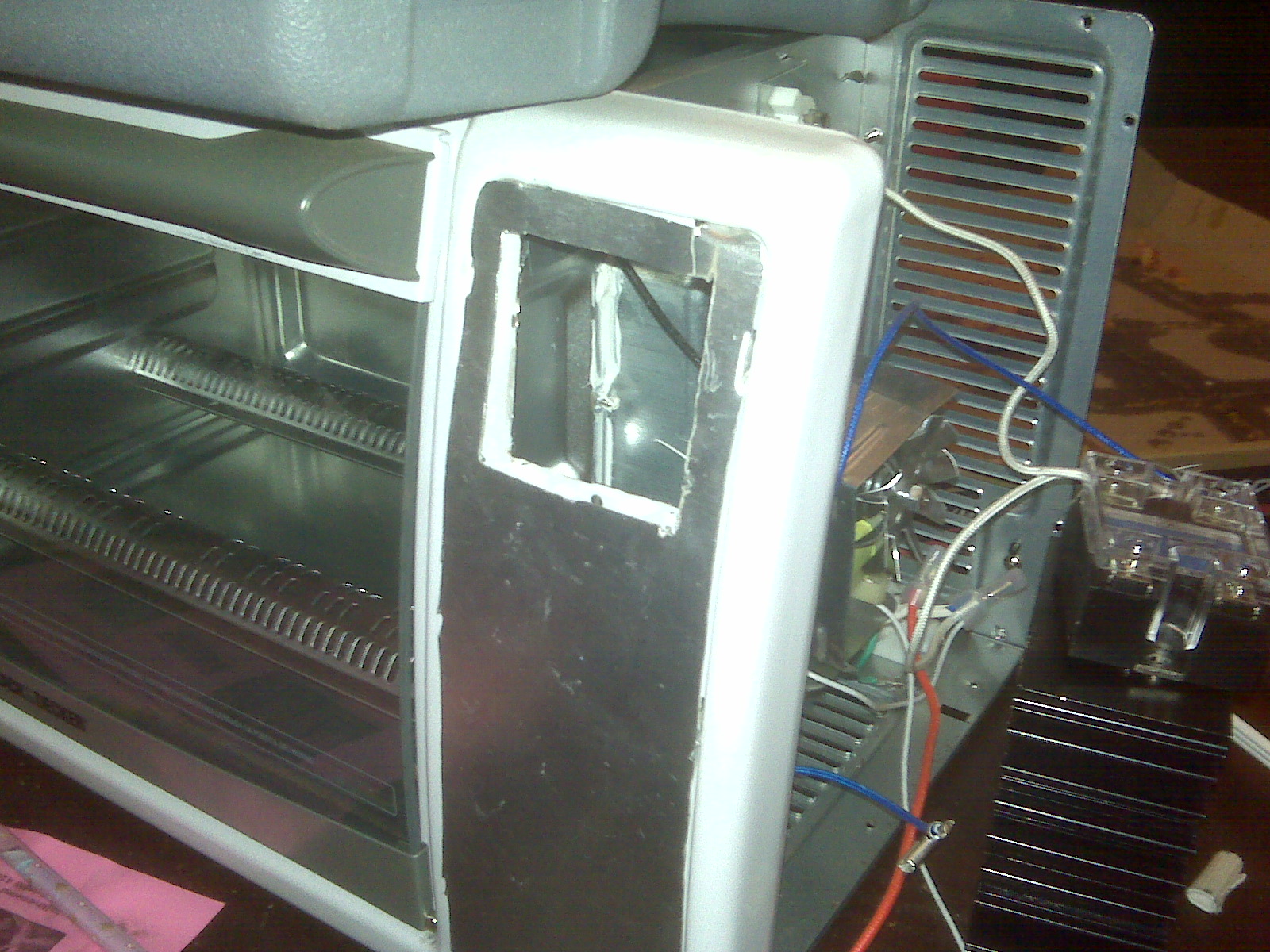
I used the old cover as a template for a new cover. I used some 25 mil (0.25 inch") Aluminum sheet that I picked up at Home Depot. Don't forget to make tabs to hold it on. File off the sharp edges when you're done cutting it out. A note - You can only bend and straighten those tabs about three or four times before they break.
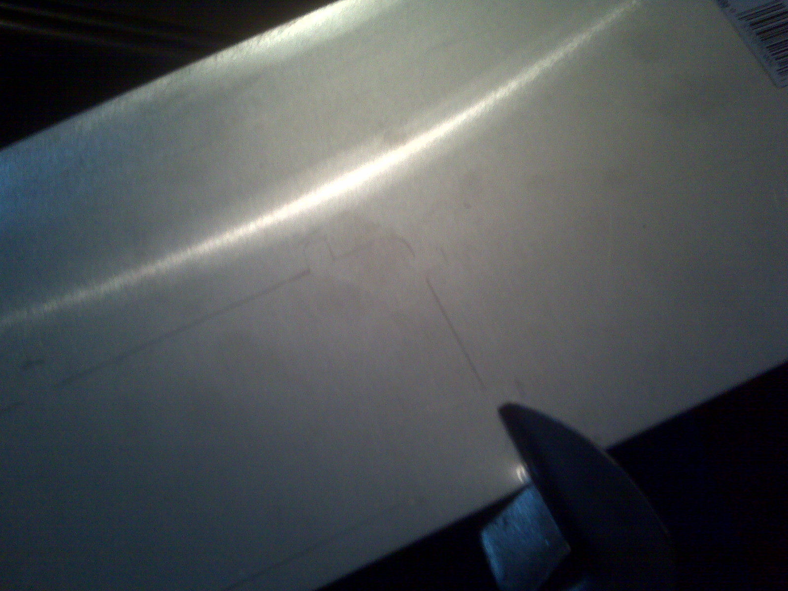
Use the ramp controller as a template...
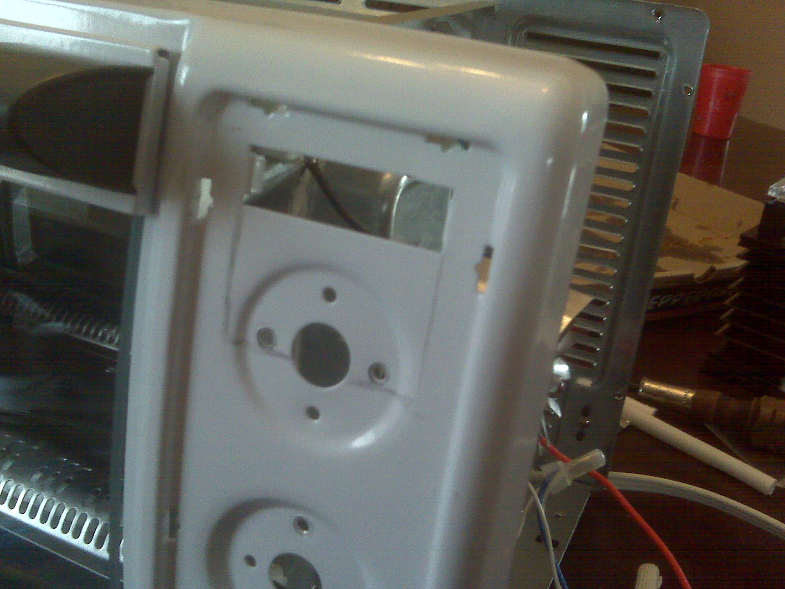
I used a Dremel Tool and cutting disks to cut the opening. WEAR SAFETY GLASSES, DIPSHIT!
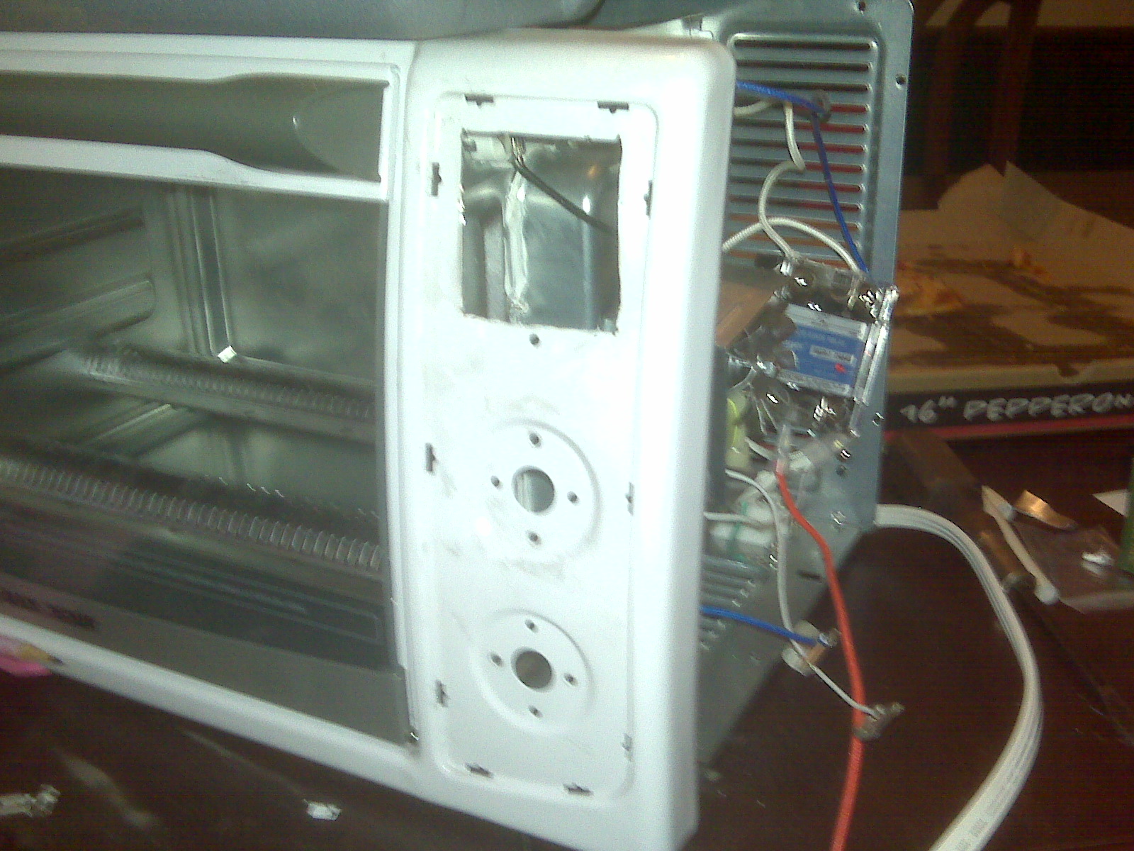
Install the new cover you made earlier...
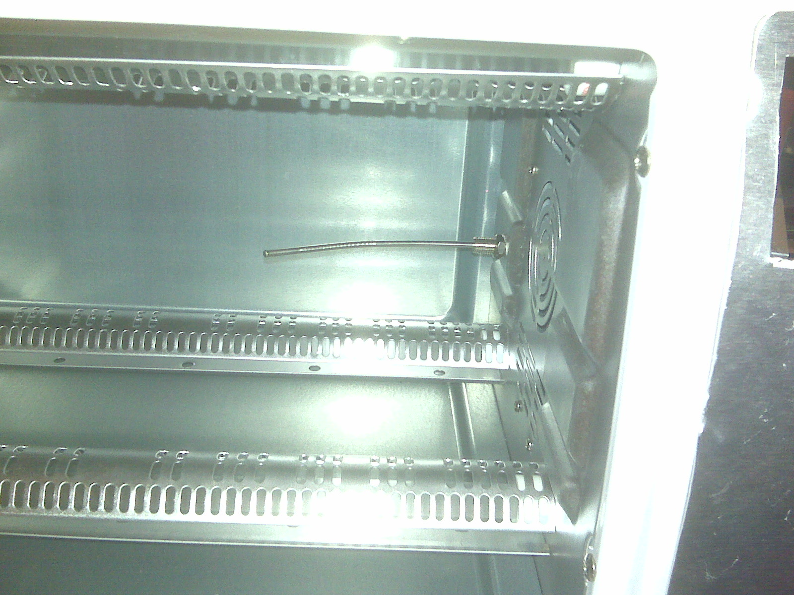
Install the thermocouple. Bend it into the airflow, just below the shelf. This requires a drill (WEAR SAFETY GLASSES, DIPSHIT!) and two 5/16" wrenches
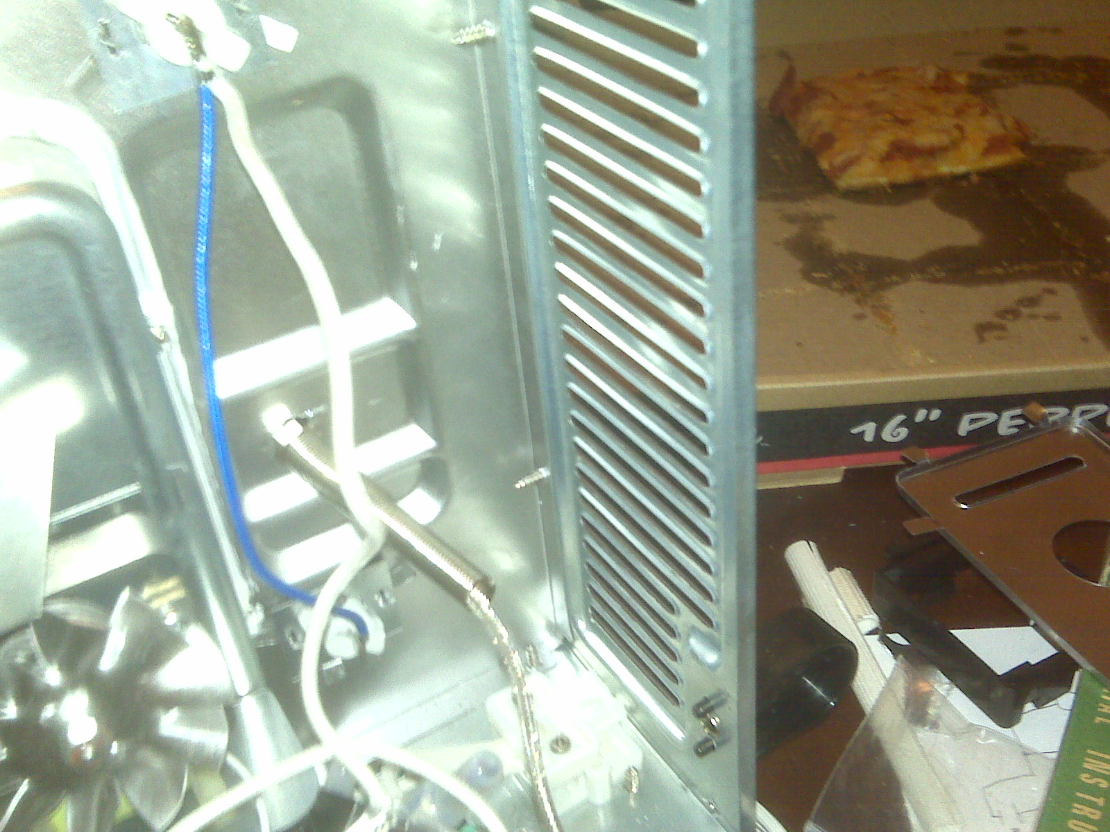
Mount the Solid State Relay (SSR) on the heat sink, using the supplied sink grease and screws. Drill some holes in the back cover (WEAR SAFETY GLASSES, DIPSHIT!) to mount the heat sink. I used 1/2" 8x32 machine screws. Ideally, I would have mounted the sink to the "floor" of the oven, but that was where the power line came in. A note - Be careful of the fan shroud... There's just enough room to install the SSR. If you position it too low, the fan will hit the shroud. If you position it too high, the heat sink will obscure a cover screw.
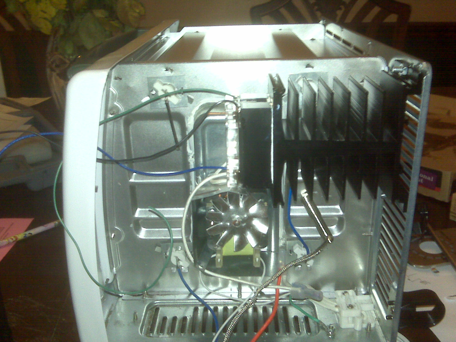
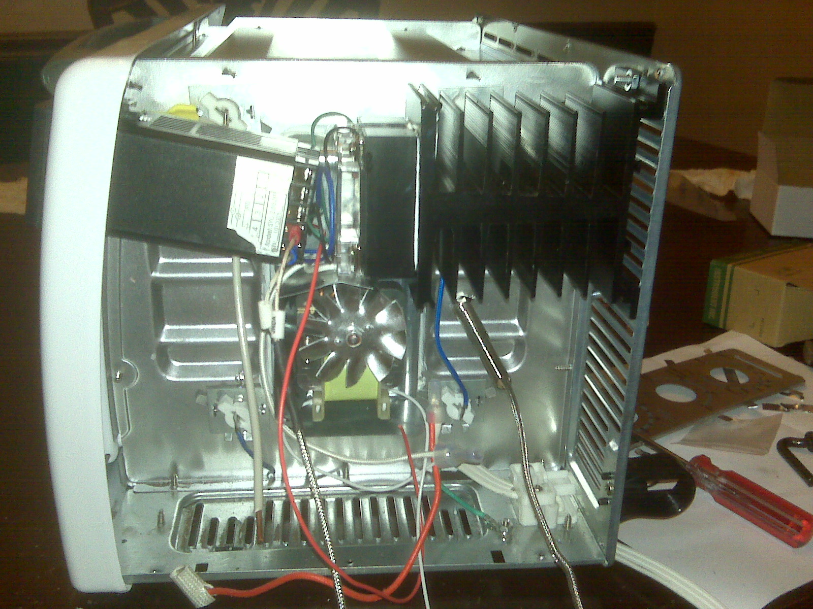
Pull the wiring through the mounting bezel (but not the thermocouple wires), and connect them to the controller. Slide the controller into the chassis. Install the bezel. Finish wiring the guts. (The schematic is here):
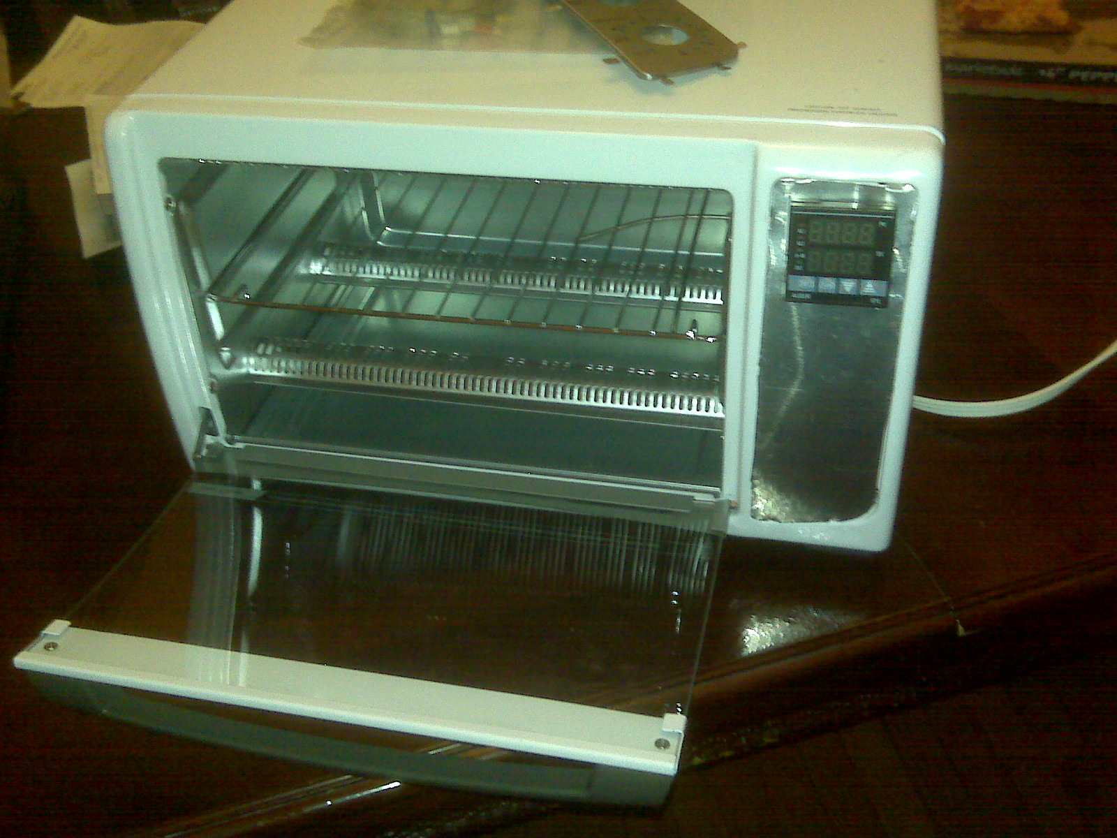
Reinstall the cover.
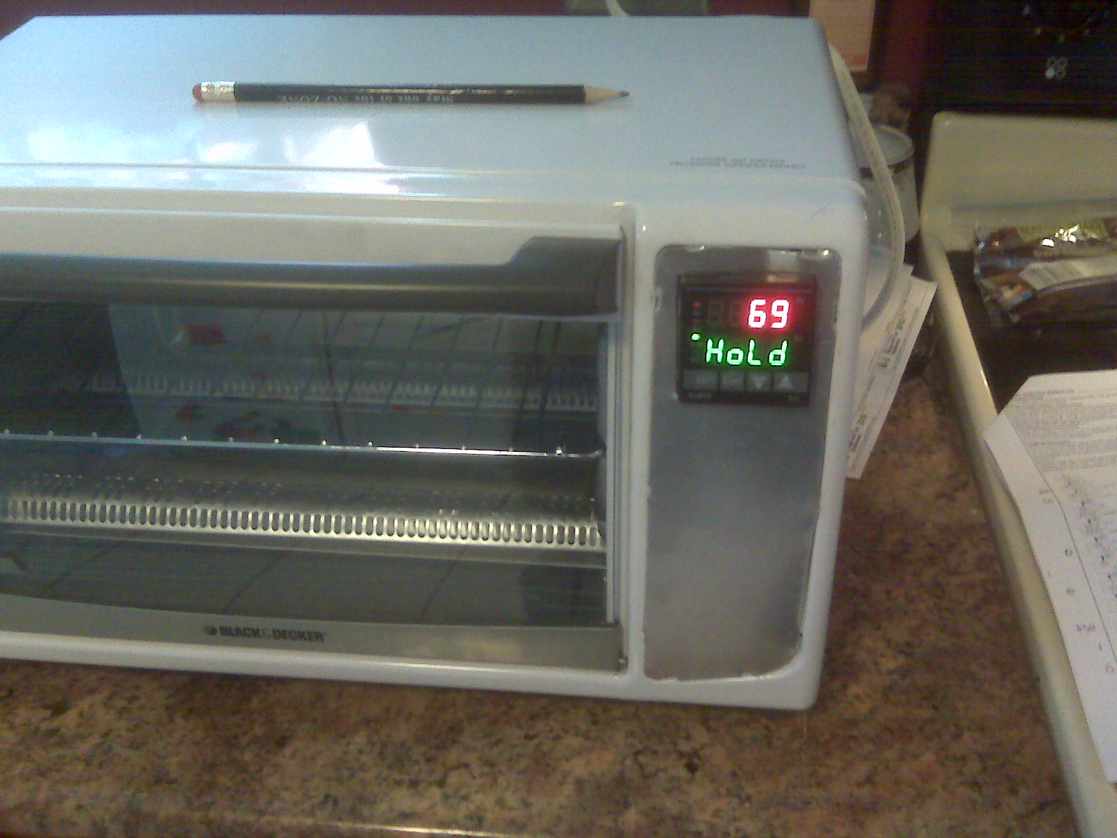
Power it on. If you did it right, no smoke will come out.
I spent the second day playing with the PID controller settings. Here is what I came up with - it gives the curve shown below (measured at 10s intervals):
| Set (Cx) | Time (tx) | Comments | |
|---|---|---|---|
| 01 | 0 | 1 | Hold at 0C for 1 min (keeps heaters off for a bit at turn on) |
| 02 | 0 | 1 | Ramp to 25C - This will start the heaters (in my house) |
| 03 | 25 | 1 | Ramp to 115C - it will overshoot |
| 04 | 115 | 2 | Hold for 2 minutes - It will actually hold near 150 |
| 05 | 115 | 2 | Ramp to 225 over the next 2 minutes - it will get to just over 235C |
| 06 | 225 | 1 | Hold for 1 minute - max temp will be reached during this hold |
| 07 | 225 | 2 | Turn off the heaters for cool down - open the oven door |
| 08 | 25 | -121 | Halt the program |
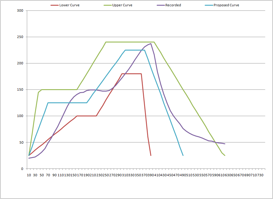
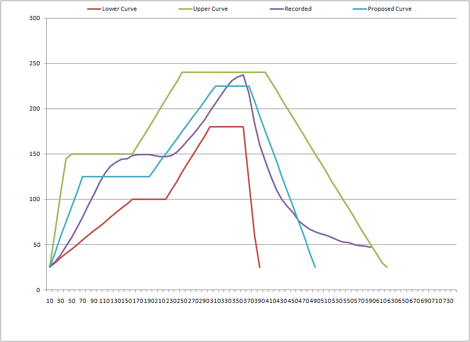
Mileage may vary, so feel free to dork with the settings to get it like you want it.